Parametric Modelling
Convert 3D mesh data into accurate, editable CAD models with our reverse engineering and parametric modelling services
Reverse Engineering & Parametric Modelling
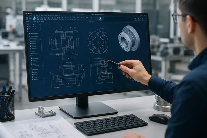
We provide reverse engineering services from 3D mesh data (.STL / .OBJ) captured using handheld scanners (white light / blue light) and ARM-based scanners such as Hexagon Romer ARM and FARO Quantum Max Arm. Our team converts mesh data into fully defined parametric CAD models suitable for design, manufacturing, and modification.
These models are used for part replication, redesign, manufacturing drawings, and legacy component reconstruction.
Our reverse engineering services help you:
- Convert 3D mesh (.STL) to parametric CAD models
- Recreate existing parts and components
- Generate manufacturing-ready drawings
- Generate manufacturing-ready drawings

Industries We Serve
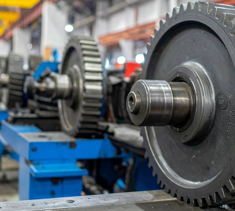
Manufacturing
Machine parts and Casting, Forging, Plastic, Rubber, any parts orcomponents

Automotive
Reverse engineering of assemblies

Aerospace
Complex geometry reconstruction
Industrial Equipment
Legacy part modelling

Consumer Products
Product redesign and replication
Why Clients Choose Our Reverse Engineering Services
Mesh to Parametric Modelling
Convert polygon mesh data into fully editable feature-based CAD models.
Accurate Geometry Reconstruction
Models built to match scanned mesh geometry with high precision.
Manufacturing-Ready Outputs
CAD models structured for direct use in production and fabrication.
Supports Complex and Freeform Shapes
Handles organic surfaces, cast parts, and intricate geometries.
Clean Feature-Based Modelling
Structured models with sketches, constraints, and feature tree.
Reliable Workflow
Step-by-step validation ensures accuracy and usability.
Our Reverse Engineering Workflow
01
Data Acquisition (Handheld / ARM Scanning)
Capture component geometry using:
- White light / blue light scanners
- Hexagon Romer ARM
- FARO Quantum Max Arm
Output: Raw mesh / scan data (.STL / .OBJ)
02
Mesh Cleanup and Optimization
Process mesh data:
- Noise removal
- Hole filling
- Mesh smoothing and decimation
Output: Clean watertight mesh
03
Mesh Alignment and Orientation
Align mesh to coordinate system and define reference planes.
04
Surface Reconstruction
Convert mesh into:
- Surface patches
- NURBS surfaces
Output: Surface model (.IGES/ .STEP)
05
Parametric Feature Modelling
Create feature-based CAD model:
- Sketch-based modelling
- Extrude, revolve, sweep features
- Dimensional constraints
Output: Fully editable parametric model
06
Assembly Modelling (if required)
Rebuild assemblies with proper component structure and relationships.
07
Deviation Analysis
Compare CAD model with mesh:
- Deviation check
- Color map analysis
Output: Inspection report (.PDF / deviation maps)
08
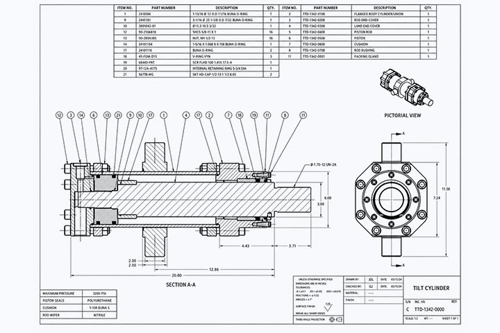
2D Drawing Creation
Generate manufacturing drawings:
- Dimensions
- Tolerances
- Section views
Output: Drawings (.DWG / .PDF)
09
Final Delivery
Provide structured CAD models ready for engineering and manufacturing use.
Deliverables
- Mesh models ( .STL / .OBJ)
- Cleaned and optimized mesh files
- Surface models (.IGES/ .STEP)
- Parametric CAD models
- Assembly models with hierarchy
- 2D manufacturing drawings (.DWG / .PDF)
- Deviation analysis reports (Color maps / inspection reports)
- Fully editable feature-based CAD files
Frequently Asked Questions
Parametric modelling is the process of converting scanned mesh data into fully editable CAD models with feature-based geometry, constraints, dimensions, and engineering-ready design structure.
Reverse engineering commonly uses mesh formats like STL and OBJ generated from white light scanners, blue light scanners, and ARM-based scanning systems.
Parametric CAD models allow engineers to easily modify dimensions, update features, create manufacturing drawings, and reuse designs for production and future engineering changes.
Reverse engineering and parametric modelling are widely used in manufacturing, automotive, aerospace, industrial equipment, and consumer product development industries.
Mesh models represent scanned geometry using polygons, while parametric CAD models contain editable features, sketches, dimensions, and engineering data suitable for manufacturing workflows.
Yes, reverse engineering workflows can accurately reconstruct organic surfaces, cast parts, freeform geometries, and highly detailed industrial components into editable CAD models.
Reverse engineering projects commonly use software like Geomagic Design X, SolidWorks, CATIA, Siemens NX, Autodesk Inventor, and other CAD modelling platforms.
Deviation analysis compares the reconstructed CAD model against the original mesh data to verify dimensional accuracy using color maps and inspection reporting tools.
Deliverables typically include cleaned mesh files, surface models, parametric CAD files, assembly models, manufacturing drawings, and deviation analysis inspection reports.
Reverse engineering helps recreate discontinued or damaged components by capturing existing geometry and converting it into accurate, editable CAD models for manufacturing and redesign.
Start your reverse engineering project today.
Need to convert 3D mesh data into parametric CAD models?
Share your mesh files or component details.
We will review and provide a clear scope and deliverables.
Headquarters
Rajkot Office
Nr. Shreeji Gau Shala, B/h Tulip Party Plot
Premvati, Vavdi, Rajkot – 360004
India
Vadodara Office
Tarsali – Danteshwar Ring Road
Vadodara – 390009
General Inquiries
© 2026 Fibrox 3D. All rights reserved. | Developed by SkyWebTech