How can engineers capture the exact shape of an existing building, industrial plant, or machine without relying entirely on manual measurements? One solution is 3D scanning.
3D scanning is a technology used to capture the geometry of physical objects and environments and convert that information into digital data. It is widely used in construction, manufacturing, architecture, infrastructure, and engineering for documentation, inspection, and design planning.
But how does a 3D scanner work, and how does it turn a real-world object into a digital model?
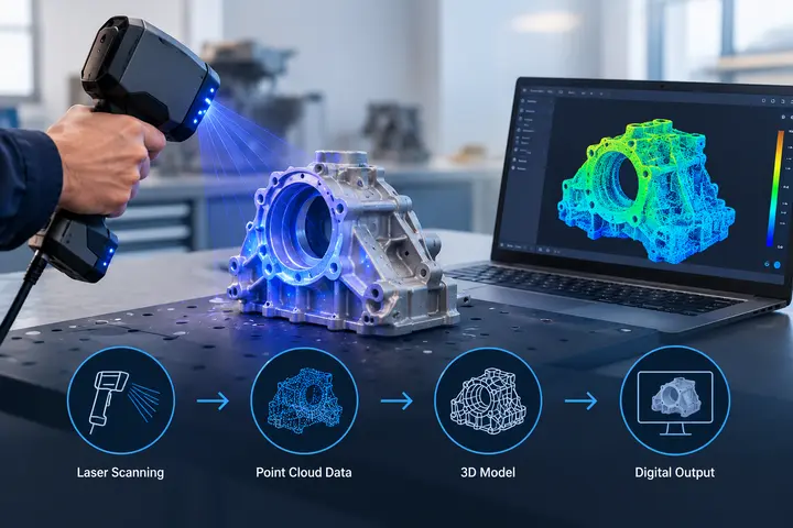
A 3D scanner collects spatial measurements using a suitable sensing technology. Specialized software then processes the measurements into a point cloud, which can be used for analysis, drawings, 3D modelling, or Building Information Modelling (BIM).
At Fibrox 3D, this process supports professional workflows that transform existing site conditions into practical digital deliverables for engineering and construction projects.
The Basics of 3D Scanning
3D scanning is the process of collecting measurements from the surfaces of physical objects or environments to represent their geometry digitally.
Depending on the equipment and method used, a scanner may capture millions of individual measurements. These measurements are processed into a collection of points called a point cloud. Each point represents a measured location in three-dimensional space, typically using X, Y, and Z coordinates. Some systems also capture colour information.
The point cloud provides a digital representation of the scanned object or site. It can be processed further to create a mesh, CAD model, BIM model, or other engineering deliverable.
3D scanning is widely used in construction, architecture, manufacturing, infrastructure, industrial facilities, and reverse engineering.
How Does a 3D Scanner Work?
Although scanning technologies differ, most 3D scanning workflows follow several main steps.
1. The Scanner Captures the Object or Environment
The first step is collecting data from the physical object, building, machine, or site.
A laser scanner sends laser pulses or beams toward surfaces and measures the returning signal. Other scanners project light patterns and analyse how those patterns appear on the surface. The system uses this information to calculate surface geometry.
For large sites, such as industrial plants or buildings, the scanner is positioned at multiple locations to capture areas that cannot be measured from a single position. Smaller objects may be scanned by moving the scanner around the component or rotating the object.
The scanning method depends on the object’s size, surface characteristics, required accuracy, and project conditions.
2. The Scanner Calculates 3D Coordinates
After capturing measurements, the scanning system calculates the position of the measured surface points in three-dimensional space.
The calculation method depends on the technology. For example, a time-of-flight laser scanner measures the time taken for a laser pulse to travel to a surface and return. A triangulation-based scanner calculates position using the known geometry between the light source, observed point, and camera or sensor.
These measurements form the geometric foundation of the 3D scan. The resulting data can represent complex shapes, equipment, structural elements, and surrounding environments.
3. The Scanner Collects Data from Multiple Positions
A single scan position cannot capture every surface. Hidden areas, corners, equipment behind obstructions, and the opposite sides of objects may remain unseen.
To improve coverage, scanning is performed from multiple positions. Each scan records the visible surfaces from its location.
For a building or industrial facility, scan positions are planned to capture the required areas while reducing blind spots. The number of scans depends on the complexity of the site, access restrictions, line of sight, and required level of detail.
4. The Individual Scans Are Registered
When multiple scans are collected, they need to be aligned into a common coordinate system. This process is called scan registration.
Registration software identifies relationships between overlapping scans and aligns their point clouds. Depending on the project, alignment may use targets, surveyed control points, or cloud-to-cloud registration methods.
The quality of registration matters because alignment errors can affect the reliability of measurements and the final model. The combined dataset should therefore be checked for gaps, misalignment, and inconsistencies before it is used for further work.
5. The Point Cloud Is Processed and Verified
After registration, the point cloud is reviewed and processed. This may involve removing unwanted points, checking coverage, reducing data density where appropriate, and verifying alignment.
Processing requirements vary by project. A highly detailed industrial survey may need dense data around pipes, equipment, and structural connections. A broader site overview may require a different balance between detail and file size.
The final dataset is checked against the project’s requirements before being used to create drawings, models, or other deliverables.
6. The Scan Data Is Converted into Usable Outputs
A point cloud is often the starting point rather than the final deliverable. Depending on project needs, it can be used to create:
- 2D as-built drawings: Plans, sections, elevations, and other drawings documenting existing conditions.
- 3D models: Digital representations of buildings, structures, machinery, or components.
- BIM models: Building information models developed from captured site conditions.
- Mesh models: Connected surfaces representing the scanned geometry.
- Inspection and measurement data: Information used to compare actual conditions with design requirements.
Fibrox 3D provides scanning and digital engineering services that help transform captured data into practical outputs for design, documentation, and engineering workflows.
Different Types of 3D Scanning Technology
Not all 3D scanners work in the same way. The most suitable technology depends on the application, required detail, scanning distance, surface properties, and working environment.
1. Time-of-Flight Laser Scanning
Time-of-flight scanners measure the time taken for a laser pulse to travel to a surface and return. Using the measured travel time and the speed of light, the system calculates the distance to the surface.
This technology is commonly used for capturing buildings, industrial plants, infrastructure, and large environments. It is useful when projects require detailed spatial documentation over relatively large areas.
2. Laser Triangulation Scanning
Laser triangulation scanners project a laser spot or line onto a surface and observe it using a sensor or camera positioned at a known angle. The system calculates the surface position using triangulation geometry.
These scanners are often used for smaller objects, manufactured components, and applications requiring detailed surface measurements. Their suitability depends on the scanner’s design, object size, surface properties, and required accuracy.
3. Structured-Light Scanning
Structured-light scanners project a known pattern of light onto an object. A camera captures the pattern as it changes across the object’s surface, and software calculates the surface geometry.
This method is used in applications such as product inspection, dimensional measurement, and detailed object capture. Performance can be affected by surface reflectivity, ambient lighting, object movement, and the characteristics of the equipment.
4. Photogrammetry
Photogrammetry reconstructs three-dimensional information from overlapping photographs taken from different viewpoints. Software identifies corresponding features across images and uses their relationships to estimate camera positions and reconstruct geometry.
Unlike laser scanning, photogrammetry relies on photographic images rather than direct laser-distance measurements. It is useful for applications such as terrain mapping, heritage documentation, and creating textured 3D models.
What Factors Affect 3D Scanning Accuracy?
The accuracy of a 3D scan depends on more than the scanner’s specifications. Several factors can influence the quality of the final data.
- Scanner specifications: Different devices have different measurement ranges, accuracy ratings, and levels of detail.
- Scanning distance: Measurement performance and point spacing can vary with distance and equipment design.
- Surface properties: Reflective, transparent, dark, or highly absorbent surfaces can make data capture more difficult for certain technologies.
- Line of sight: Objects hidden behind other surfaces cannot be captured from a given scan position.
- Environmental conditions: Movement, vibration, lighting, weather, and site conditions can affect certain scanning methods.
- Registration quality: Poor alignment between scan positions can introduce errors into the combined dataset.
- Data processing: Incorrect filtering, modelling assumptions, or inadequate verification can affect the final deliverable.
For this reason, the required accuracy should be defined before scanning begins. Equipment selection, scan planning, field procedures, registration, and quality checks should all support the project’s measurement requirements.
Common Applications of 3D Scanning
3D scanning supports a wide range of industries by providing digital information about existing objects and environments.
Architecture and Construction
Scanning captures existing buildings and site conditions for renovation, refurbishment, design coordination, and as-built documentation. It can reduce dependence on manual measurements, particularly in complex spaces.
Industrial Plants and Facilities
Industrial scanning records equipment, pipes, structures, and plant layouts. The data can support modifications, maintenance planning, facility upgrades, and documentation of existing installations.
Manufacturing and Quality Inspection
Manufacturers can use 3D scanning to capture component geometry and compare measured shapes with design references. The usefulness of the comparison depends on the scanning system, inspection method, and defined tolerances.
Reverse Engineering
When original drawings or CAD files are unavailable, scanning can help capture a component’s existing geometry. The data can then be processed to support the creation of a suitable CAD model.
Infrastructure and Surveying
Scanning can document bridges, roads, utilities, and other infrastructure. The captured data supports measurement, condition documentation, and planning, subject to the coverage and accuracy required for each project.
How to Choose the Right 3D Scanning Method
Choosing a scanning method begins with understanding what needs to be captured and how the data will be used.
Consider the following questions:
- What is the size of the subject? Large buildings and industrial facilities may require a different system from small mechanical components.
- What level of detail is required? Inspection, design, documentation, and modelling projects may have different accuracy requirements.
- What are the surface conditions? Reflective, transparent, or dark surfaces may require additional planning or a different capture method.
- What output is needed? Point clouds, CAD models, BIM models, mesh models, and as-built drawings require different processing workflows.
- What are the site constraints? Access, movement, lighting, safety, and line of sight can influence the method and scan plan.
The best solution is the one that meets the project’s technical requirements and produces data that can be used effectively in the next stage of work.
Conclusion
A 3D scanner works by capturing surface measurements or image information and converting it into digital three-dimensional data. Depending on the technology, this data can be processed into point clouds, drawings, mesh models, CAD models, or BIM deliverables.
Successful scanning involves more than collecting measurements. Careful planning, suitable equipment, complete site coverage, accurate registration, and data verification all contribute to useful results.
At Fibrox 3D, scanning and digital engineering workflows help clients document existing conditions and prepare data for design, construction, and engineering applications. If your project requires 3D scanning, point cloud processing, as-built documentation, or BIM modelling, contact Fibrox 3D to discuss your requirements.
FAQs
1. How does a 3D scanner measure an object?
Ans: A 3D scanner captures surface information using technologies such as laser measurement, triangulation, or structured light. Software converts the measurements into three-dimensional coordinates.
2. What is the output of a 3D scanner?
Ans: The primary output is often a point cloud. Depending on the project, it can be processed into 2D drawings, 3D models, BIM models, or mesh data.
3. Is 3D laser scanning more accurate than photogrammetry?
Ans: Neither method is universally more accurate. Performance depends on the equipment, capture conditions, processing workflow, and accuracy requirements of the project.
4. Can 3D scanning be used for BIM modeling?
Ans: Yes. Point cloud data can be used as a reference for creating BIM models of existing buildings and facilities. Model detail depends on project requirements and the agreed level of development.
5. Which industries use 3D scanning?
Ans: Industries including construction, architecture, manufacturing, infrastructure, industrial plants, and product development use 3D scanning for documentation, measurement, inspection, and modelling.