Capturing the exact geometry of a physical object is essential for quality inspection, product development, and reverse engineering. Traditional measurement methods can be time-consuming, especially when working with complex shapes, intricate details, or freeform surfaces. This is where modern 3D scanning technology offers an effective alternative.
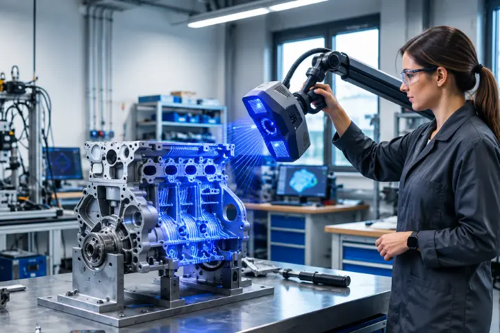
Structured blue light scanning is a non-contact measurement technique that uses projected light patterns and cameras to capture an object’s surface geometry. It can produce detailed 3D data for applications such as dimensional inspection, product design, and digital modeling.
In this guide, Fibrox 3D explains how structured blue light scanning works, its key benefits, common applications, and the factors to consider when selecting a suitable 3D scanning solution.
What is Structured Blue Light Scanning?
To work, the structured blue light scanning method emits a very generic light pattern just outside the visible spectrum that most likely produces an interference pattern. As the interference pattern scans the surface of the object, the cameras will capture the distortion of that blue light pattern in order to reconstruct very fine 3D geometric details and generate 3D models.
- A structured light scanner uses optical triangulation instead of laser beams or touch probes as a traditional means of scanning.
- The term structured light refers to the way the light is patterned, usually as stripes.
- “Blue light” is chosen because of the shorter wavelength, which will help reduce interference from ambient light and increase the accuracy of scans.
A look at the industry trend in India shall find the movement toward blue light scanners, especially in the hands of professional 3D scanning service providers, primarily attributed to high resolution and efficiency.
How Structured Blue Light Scanning Works: Step-by-Step
The structured blue light scanning process involves several stages, from preparing the object to processing the captured measurements into usable 3D data.
1. Preparing the Object
The object is inspected before scanning begins. Dust, loose particles, and surface contaminants may need to be removed to avoid affecting the captured data.
Highly reflective, transparent, or translucent surfaces can present challenges for optical scanners. Depending on the material and equipment, specialized scanning settings or a removable matte coating may be required.
The preparation method depends on the object’s surface properties and the accuracy requirements of the project.
2. Setting Up the Scanner
A structured light scanning system generally consists of a light projector, one or more cameras, calibration data, and processing software.
The scanner is positioned at a suitable distance and angle based on the object’s size, geometry, and the equipment manufacturer’s specifications. Calibration helps establish the geometric relationship between the projector and cameras, supporting reliable measurements.
3. Projecting Blue Light Patterns
The projector casts a sequence of controlled blue light patterns, such as stripes or other coded patterns, onto the object’s surface.
As the patterns fall across curved, raised, recessed, and angled areas, their appearance changes according to the surface geometry. These changes provide information that the scanning system uses to calculate the object’s shape.
4. Capturing Data and Calculating 3D Coordinates
The cameras capture images of the projected patterns from known positions relative to the projector.
Using optical triangulation and pattern-processing algorithms, the software calculates the 3D coordinates of points on the visible surface. Multiple captures may be needed to cover different sides or hidden areas of the object.
The individual measurements are then aligned and combined to create a more complete representation of the scanned surface.
5. Processing the 3D Data
The captured measurements are processed into a point cloud, which represents the object’s surface using individual 3D points.
Depending on the project requirements, the point cloud can be converted into a polygon mesh made up of connected vertices and faces. The data may also undergo alignment, noise removal, hole filling, and other processing steps.
The final output can support dimensional inspection, CAD modeling, reverse engineering, or 3D printing. The required file format depends on the intended application and downstream software.
Key Benefits of Structured Blue Light Scanning
Structured blue light scanning offers several advantages for applications that require detailed surface measurements.
High-Resolution Surface Capture
Suitable structured light scanners can capture fine geometric details, making them useful for intricate components, small features, and complex surfaces. Actual accuracy and resolution depend on the scanner specifications, measuring volume, calibration, and scanning conditions.
Non-Contact Measurement
Because the scanner measures an object optically, it does not need to touch the surface. This is beneficial when measuring delicate components or objects where physical contact could affect the measurement.
Efficient Data Collection
Structured light systems can capture many surface points in a short period. This can reduce the time required to document complex geometry compared with collecting individual measurements manually.
Support for Inspection and Reverse Engineering
The resulting 3D data can be compared with reference CAD models to identify dimensional deviations. It can also provide a foundation for reconstructing geometry when original design files are unavailable.
Detailed Digital Documentation
The captured geometry can be stored for further analysis, product development, quality records, and future design work.
Applications of Structured Blue Light Scanning
Structured blue light scanning is used across industries where detailed component measurements and digital surface data are valuable.
- Manufacturing and quality inspection: Manufacturers can measure component geometry, inspect surface features, and compare manufactured parts against design specifications.
- Automotive and aerospace: Engineers can capture complex component shapes for dimensional verification, product development, and reverse engineering, subject to the required measurement tolerances.
- Product design and development: Designers can digitize physical prototypes to support design modifications, fit checks, and the development of improved components.
- Jewelry and precision objects: Suitable systems can capture intricate shapes and fine details for digital modeling and design reproduction.
- Research and cultural preservation: Non-contact scanning can help document suitable artifacts and objects for digital archiving, study, and preservation.
- Tooling and component reconstruction: Scan data can help recreate existing parts, inspect worn components, and support the development of replacement designs.
The most suitable scanning method depends on the object’s dimensions, surface material, required accuracy, accessibility, and intended output.
Structured Blue Light Scanning vs. Laser Scanning
Structured blue light scanning and laser scanning both capture 3D geometry without requiring direct contact, but they use different measurement approaches.
Structured blue light scanners project light patterns and analyze their deformation using cameras. Many systems are well suited to detailed measurements of components and complex surfaces.
Laser scanning systems use laser-based measurement techniques, with their capabilities varying according to the equipment design. Different systems can be suited to applications ranging from detailed component inspection to larger objects, buildings, and industrial environments.
Neither method is universally better. The right choice depends on the measurement scale, surface characteristics, working environment, accuracy requirements, and deliverables.
For projects involving existing buildings, industrial facilities, or large physical environments, explore Fibrox 3D’s laser scanning services to understand how 3D laser scanning can support as-built documentation and digital modeling.
How to Choose the Right 3D Scanning Solution
Before selecting a scanning system or service, consider the following factors:
- Project requirements: Define the object’s size, geometric complexity, required tolerances, and intended use of the data.
- Surface characteristics: Identify reflective, dark, transparent, or translucent surfaces that may affect optical measurement.
- Equipment capabilities: Review the scanner’s documented accuracy, resolution, measuring volume, and suitability for the application.
- Data processing: Confirm whether the project requires a point cloud, polygon mesh, CAD model, inspection report, or another deliverable.
- Technical expertise: Choose a provider with relevant experience in scanning, data processing, and the engineering requirements of your project.
- Quality validation: Ask how the measurements will be checked and whether the proposed workflow can meet the required tolerances.
At Fibrox 3D, selecting the appropriate 3D measurement approach starts with understanding the project, the physical environment, and the final data requirements. Matching the technology to these needs helps establish a practical workflow for accurate digital documentation.
Conclusion
Structured blue light scanning provides a valuable way to capture detailed surface geometry without physically touching an object. By projecting controlled light patterns and processing their deformation through optical triangulation, the technology creates 3D data that can support inspection, product development, and reverse engineering.
Its effectiveness depends on choosing suitable equipment, preparing the object correctly, and processing the captured data according to the project’s requirements.
For businesses evaluating 3D scanning technology, understanding the differences between structured light and laser scanning is an important step toward selecting the right solution. Fibrox 3D provides 3D scanning-related solutions for engineering, documentation, and digital modeling projects. Visit Fibrox 3D to explore the available services and identify an approach suited to your project.
Frequently Asked Questions
1. How does structured blue light scanning work?
Ans: It projects controlled blue light patterns onto an object’s surface. Cameras capture pattern deformation, and software uses optical triangulation to calculate the object’s 3D geometry.
2. Why is blue light used in structured light scanning?
Ans: Blue light’s relatively short wavelength can help some scanners reduce the influence of ambient light. Performance depends on the scanner design and measurement conditions.
3. What types of objects can be scanned using structured blue light?
Ans: Suitable scanners can capture small components, intricate shapes, and complex surfaces. Reflective, transparent, or translucent objects may require special preparation.
4. What is the difference between structured light scanning and laser scanning?
Ans: Structured light scanning analyzes projected patterns using cameras, while laser scanning uses laser-based measurement techniques. The best method depends on the application and measurement requirements.
5. Can structured blue light scanning be used for reverse engineering?
Ans: Yes. The captured point cloud or mesh can help reconstruct existing component geometry and support CAD modeling, provided the data meets the project’s accuracy requirements.